Air Cooled Heat Exchanger selection matters when plants must reject heat without relying on large cooling-water supplies. In 2026, operators are comparing designs for refineries, power stations, gas processing, and data infrastructure. The International Energy Agency’s Electricity 2024 report says electricity use by data centres, artificial intelligence, and cryptocurrency could exceed 1,000 terawatt-hours by 2026. That figure is not a heat-exchanger forecast, but it highlights growing pressure on cooling systems and power networks. Every design still faces a basic trade-off: heat-transfer performance, fan power, footprint, noise, and maintenance access.
This guide examines the main types, including forced-draft and induced-draft units, natural-draft systems, and common finned-tube configurations. It explains where each arrangement can fit, from a compact process skid to a broad refinery bay. Fan placement changes airflow and maintenance access. Bundle layout affects cleaning and temperature performance. These details matter on site.
No single type is best everywhere. Ambient temperature, process conditions, dust, available plot space, and operating hours can change the answer. Even published market estimates can use different definitions, so headline growth figures deserve a careful read. A sound comparison starts with the duty and local conditions, then checks lifecycle costs and reliability. The goal is practical: identify which exchanger designs deserve closer engineering review in 2026.
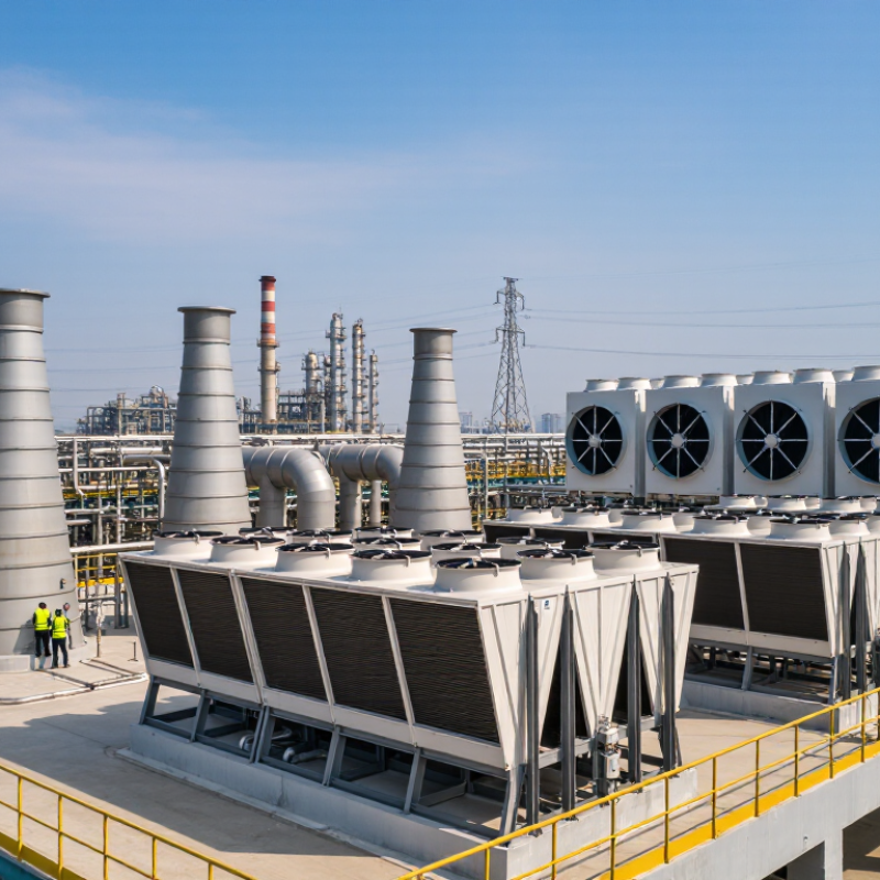
API 661 defines requirements for air-cooled heat exchangers used in petroleum, petrochemical, and natural gas service. It addresses design, materials, fabrication, inspection, testing, and documentation. Project specifications still matter; the standard does not choose every detail for a particular duty.
The main assembly includes a finned-tube bundle, headers, fans, drives, a plenum, and a supporting structure. Process fluid flows through the tubes, while ambient air passes over the external fins. Fans may push air through the bundle in a forced-draft arrangement or draw it through in an induced-draft arrangement. Small details matter. Header access, tube spacing, and fan clearance can affect maintenance and operation.
Forced draft can simplify access to the fan and drive, while induced draft can help disperse heated discharge air. Neither arrangement is best for every site. Wind, noise limits, fouling, and available maintenance space all influence the choice. API 661 provides a common engineering framework, but designers must still check the actual operating conditions and specified edition. A detail that looks minor on a drawing may be awkward to inspect in the field. That deserves another review.

An air-cooled heat exchanger is not rated by surface area alone. Start with the process-side duty: Q = ṁCpΔT, where mass flow, heat capacity, and the fluid’s allowable temperature change define the heat load. Keep units consistent. For example, cooling oil from 140°C to 100°C gives a 40°C temperature change, but does not determine the required fan airflow. The air-side balance also depends on inlet-air temperature and air mass flow, because air warms as it crosses the finned tubes.
Temperature approach is the difference between the process outlet temperature and the cooling air temperature available to the exchanger. A tighter approach usually demands more heat-transfer area, greater airflow, or both. Forced-draft and induced-draft arrangements can deliver similar duty, yet fan position affects air distribution and recirculation risk. Easy to miss. Check peak summer conditions, not just a mild-day rating. Wind, dust on fins, and uneven airflow can weaken a calculated result; field readings may reveal gaps between the model and actual performance. A rating should state its ambient conditions and fouling assumptions clearly.
Forced-draft coolers place fans beneath the tube bundle. They push ambient air upward across the tubes. Fan components usually handle cooler air, and ground-level access can simplify inspection. But nearby structures may obstruct the inlet. Poor clearance can also pull warm discharge air back into the cooler.
Induced-draft coolers position fans above the bundle. They draw air through the tubes and release it upward, which can help reduce hot-air recirculation. The fan sees warmer, moist discharge air, however, and maintenance may require elevated access. That trade-off is easy to underestimate. Neither layout is automatically better; wind, plot space, noise limits, and operating temperatures all matter.
Tips: Check airflow around the entire unit, not just at the fan. Look for walls, pipe racks, and nearby exhausts. Confirm safe access for fan and motor maintenance. A simple rule can mislead: site conditions often decide which draft arrangement performs better.
Fan position determines the airflow direction through the tube bundle.
Forced draft: The fan is upstream of the bundle and pushes air through it. Induced draft: The fan is downstream and pulls air through the bundle. Schematic only; not to scale.
Natural-draft air coolers move air through buoyancy, not fan power. Warm air rises through a tall structure, drawing cooler ambient air across heat-transfer surfaces. The arrangement can reduce operating noise and avoid large fan drives. Quiet operation matters near occupied areas. But natural draft depends on temperature difference, wind, and structure height. On mild days, airflow may fall while process duty remains high. Designers therefore check seasonal conditions, not only peak summer temperatures.
Hybrid coolers combine buoyancy flow with mechanical fans. Fans can support airflow during hot weather or high-load periods, then slow down when natural draft is sufficient. This can balance heat rejection, electrical demand, and sound levels, though controls add complexity. A practical review compares required duty with ambient dry-bulb temperature, outlet temperature targets, fouling risk, and available plot space. Fan access and maintenance clearances deserve attention too. A few degrees matter. In field operation, wind patterns or unexpected dust can upset clean design assumptions. That is worth admitting early. For variable-duty plants, operators should confirm how the unit responds when fans are staged, unavailable, or running at reduced speed. The best choice depends on the duty profile, site conditions, and tolerance for mechanical upkeep.
| Type | Airflow driver | Typical configuration | Typical duty and applications | Key advantages | Main considerations |
|---|---|---|---|---|---|
| Natural-draft dry cooler | Warm air becomes less dense and rises through a tall stack or chimney, drawing cooler ambient air through the heat-transfer bundle. | Large vertical or inclined finned-tube banks arranged around or beneath a stack; no main fans are required. | Continuous heat rejection where substantial plot area and structure height are available, especially for large, steady process or power-generation duties. | No large fan motors; low fan-related maintenance and noise; airflow can continue without mechanical fan operation. | Airflow depends on ambient temperature, wind, stack height, and temperature difference. The structure is large, and output is less readily adjusted than with fan-driven equipment. |
| Natural-draft air-cooled condenser (ACC) | Buoyancy-driven airflow passes through condenser bundles, while steam condenses inside the tubes. | Elevated finned-tube bundles connected to steam-distribution and condensate-collection systems, with a large natural-draft structure. | Condensing turbine exhaust steam in power-generation service where a dry cooling system is selected. | Uses air rather than a continuous evaporative cooling-water supply; avoids the large fan arrays used in conventional forced-draft ACCs. | Performance is sensitive to ambient conditions and wind. Large structures and bundle layouts require careful design to manage recirculation and uneven airflow. |
| Fan-assisted natural-draft cooler | Buoyancy provides baseline airflow; fans supplement or control airflow when natural draft alone is insufficient. | A stack or chimney combined with fan-assisted air entry or booster fans, depending on the design. | Variable-duty installations that need additional airflow during warm weather, peak loads, or periods of weak natural draft. | Can combine low fan use in favorable conditions with added airflow when needed; offers more operating flexibility than a purely natural-draft unit. | Fans, drives, and controls add capital cost, power use, noise, and maintenance. The actual benefit depends on the operating profile and system design. |
| Wet-dry hybrid cooler | Typically uses mechanically driven airflow; heat is rejected through a dry section, with a wetted or evaporative section used when additional cooling is required. | Dry finned-tube surfaces combined with an evaporative section, such as wetted media or a spray-assisted stage. | Applications seeking dry operation for much of the year while using evaporative assistance during high ambient temperatures or peak duty. | Can reduce water use compared with continuous evaporative cooling and can improve hot-weather heat-rejection capability compared with dry-only operation. | Uses water during evaporative operation and requires water treatment and maintenance. Performance and water consumption depend on climate, controls, and operating hours. |
Note: These descriptions are qualitative. Actual capacity, airflow, water use, and operating cost depend on the process duty, ambient conditions, equipment geometry, and control strategy.
Air-cooled heat exchangers use finned tubes to increase air-side heat transfer, but fin construction affects cost, durability, and maintenance. Extruded fins are formed from an outer tube, creating a tight mechanical bond with the inner tube. They suit many general services, though deep fins can collect dust and become harder to clean. Embedded fins use a helical strip seated in a groove, offering a firm attachment for demanding temperatures and vibration. Integral-fin tubes are machined from one piece of metal, avoiding a separate fin-to-tube contact point. They can be robust, but their lower fin height may limit surface area in compact bundles. The best choice depends on fluid conditions, ambient air, and cleaning access. Details matter.
API Standard 661 provides design requirements for air-cooled heat exchangers used in petroleum and natural-gas service. The International Energy Agency’s 2018 report, The Future of Cooling, projects global energy demand for space cooling could more than triple by 2050, reaching 6,200 TWh. That figure concerns building cooling, not process exchangers, but it underscores growing pressure to manage heat efficiently. In practice, dusty sites may favor easier-to-clean fin geometry, while corrosive atmospheres call for careful material selection and inspection. There is no universal winner. Even a well-selected fin can underperform when airflow is uneven or fouling goes unnoticed.